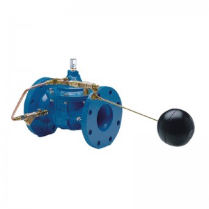
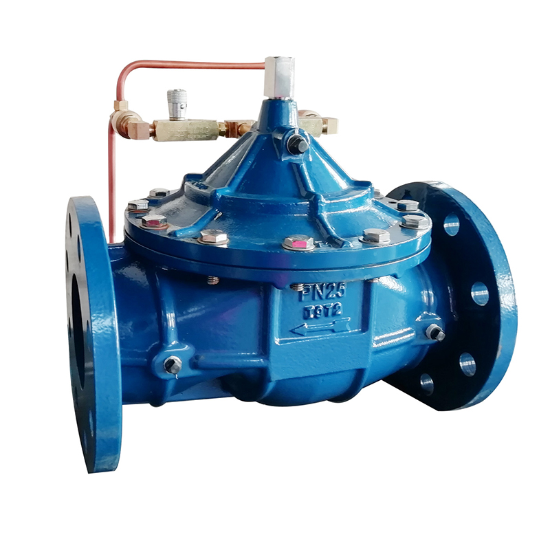

Material of main parts:
| Parts No. | Name | Material |
| A | Main Ball | Cast Iron, Ductile Iron |
| B | Ball | Brass |
| B1 | Ball | Brass |
| C | Exhaust Valve | Brass |
| D | Ball | Brass |
| G | Filter | Brass |
| E | Throttle Valve | Brass |
| Vertical installation spring assembly (optional) Stainless Steel | ||

Size Dn50-300 ( over Dn300, please contact us. )
Pressure setting range: 0.35-5.6 bar ; 1.75-12.25 bar ; 2.10-21 bar
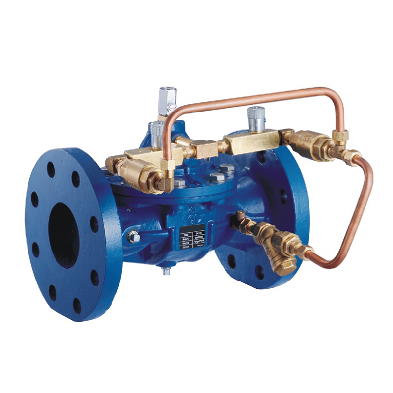
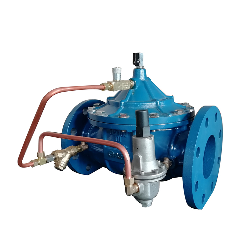
Working principle
When pump starts, the upstream pressure goes up resulting in pressure increase on the lower side of the main valve membrane. The closing system rises gradually and valve opens slowly. The speed of opening can be adjusted by a needle valve C on the pilot system (located on upper branch of pilot system on scheme above)

When pump stops or in case of backfoot the downstream pressure goes up resulting in a pressure increase on the upper side of the main valve membrane. The closing system drop down gradually and the valve closes slowly. The speed of the closure can be adjusted by a needle valve C on the pilot system (located on below branch of pilot system on scheme above)
The control valve is function as hydraulic check valve, which opens and closes at a controllable and regulated speed of needle valve, reducing sudden jump in pressure
Application examples
1. Isolation valve of the by-pass
2a-2b Isolation valves of the main water pipe
3. Rubber expansion joints
4. Strainer
5. Air valve
A .SCT 1001 control valve

Matters needing attention
1. Strainer should be installed in the upstream of the control valve to ensure good water quality.
2. The exhaust valve should be installed in the downstream of the control valve to exhaust the mixed gas in pipeline.
3. When the control valve is mounted horizontally, the maximum inclination angle of the control valve can not be exceed 45°.